
Redundancy challenges in Tier III/IV-aligned colocation data centers don’t always come from lack of capacity. You can have “enough” UPS modules, “enough” generators, and a clean N+1 or 2N story—and still end up explaining to multiple tenants why their “independent” paths dropped together. It usually isn’t a capacity problem. It’s a separation problem: shared bypass paths, coupled control logic, and maintenance transitions that quietly merge fault domains at the exact moment you need them to stay apart. The only way to prevent this is to keep decision-making and bypass behavior bounded within independent domains, so transitions remain local instead of propagating across tenants. The sections below examine where redundancy collapses and how architectural separation preserves availability during real operating states.
Reading time: 7 minutes
Where multi-tenant outages actually start
- Two paths become one event
- Bypass becomes the choke point
- Controls synchronize the wrong action
- Maintenance windows remove your margin
- Tier claims hide shared dependencies
The redundancy math that still lets you fail
The uncomfortable truth is that redundancy in N+1 and 2N can be “true” and still irrelevant, because the outage is driven by where paths converge, not how many boxes exist. This is where vendor diversification fails in practice: you think you bought two independent trains, but one shared node or shared decision path turns them into one effective fault domain.
This shows up when a “clean” A/B design still depends on the same bus segment, tie point, or transfer function in at least one operating state you actually enter. The moment a local UPS event or switchgear anomaly hits that shared element, both sides inherit the same constraint and the incident stops being tenant-scoped.
The only way this stays manageable is if fault-domain separation is treated as a UPS design requirement to eliminate SPOFs, not a procurement outcome—and it has to be true in the states you operate in, not just the normal one-line. Tier III and Tier IV are availability objectives, not immunity claims, and they only hold when redundancy survives maintenance and transition states.
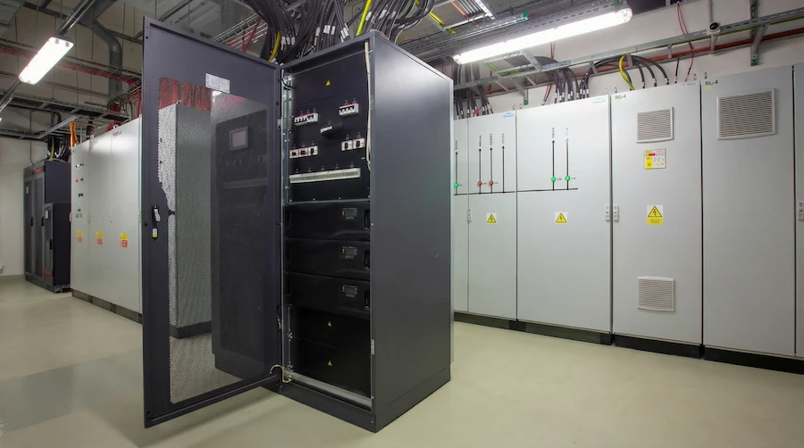
The bypass node that quietly merges tenants
Redundant paths often converge before distribution. A UPS typically feeds a single output into a PDU, and that PDU then distributes multiple tenant paths. On paper, downstream A/B separation looks intact, but upstream of the PDU the load already depends on one transfer behavior.
This matters during bypass events. If the UPS enters static or maintenance bypass, the entire downstream distribution inherits that transition simultaneously. What appeared as independent tenant paths becomes a single electrical event defined at the UPS output.
The risk increases during maintenance and recovery, when bypass functions are exercised more frequently. A protection action, transfer sequence, or switching anomaly at that point can propagate across multiple tenants, not because distribution is shared, but because the convergence already occurred before it.
This is why bypass architecture inside the UPS becomes critical. When bypass behavior is centralized at a common output, transitions affect the full downstream domain. When bypass behavior is distributed and bounded within independent paths, a local event remains local, even when loads are fed from a common distribution layer.
The difference is rarely visible on a one-line. It only appears during transitions, when the location of the bypass decision defines whether redundancy isolates the event or propagates it.
If you’re not sure whether your A/B paths stay independent during bypass, maintenance, and abnormal states, the Redundancy Architecture Guide walks through the merge points that most one-lines hide.
It includes vendor evaluation questions, fault-domain examples, and architecture checks used to validate tenant isolation in live colocation environments.
When every module makes the same wrong decision
You can separate copper and still couple outcomes. Independent electrical paths can fail together when one shared control decision drives them into the same wrong state at the same time. Now the control plane is your common-mode risk: “two paths” become “one brain.”
This shows up when shared PLCs, shared SCADA dependencies, shared interlocks, or shared communications coordinate actions across both sides. In practice, this can translate into a single control layer for multiple generators or a shared control board influencing multiple UPS paths. One bad signal, one configuration error, one network partition, or one shared permissive can simultaneously inhibit correct operation across multiple “independent” power trains—so the system responds as a synchronized machine instead of two isolated domains.
Fault domain separation has to include decision authority, not just power flow. That means each domain must be able to sense, decide, and act without relying on shared logic that can fail once and affect many. The hard part is that you don’t see the coupling until you test abnormal inputs, and most commissioning scripts never push the control plane into the states that create the real blast radius.
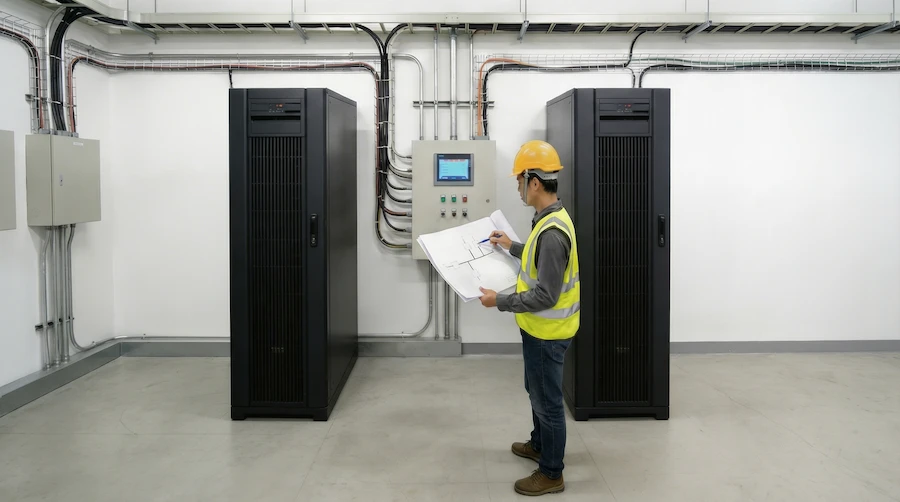
The maintenance window that ends up owning you
Transitions consume redundancy and expose hidden coupling. The moment you enter bypass, override an interlock, or shift operating modes, you’re no longer operating the system you validated on paper—you’re operating a temporary topology with reduced margin and altered protection/logic behavior.
A routine switching sequence becomes a multi-tenant event when one planned constraint overlaps with one unplanned disturbance. That second event is often small: a nuisance trip, a transient, an operator correction, a breaker that doesn’t behave exactly as expected. But in a constrained configuration, the shared bypass path or coupled logic turns that overlap into propagation.
This is where most N+1 designs quietly fail: they were never required to preserve isolation during transition states. Maintenance states have to be treated as first-class operating modes with their own fault-domain maps—otherwise the plant is “redundant” right up until the day you need to touch it.
The part nobody checks until it fails
Redundancy counts miss hidden shared nodes that only appear in certain configurations. If you want to know whether your Tier III/IV-aligned story survives contact with operations, the question isn’t “Do we have enough equipment?” It’s “In this state, what single thing can still drop more than one tenant path?”
This shows up when teams rely on a single one-line and a single operating narrative, then discover after an incident that domains merged in bypass, recovery, or an abnormal mode. The merge points are usually few—and they’re usually exercised repeatedly during maintenance—so the same outage pattern keeps reappearing under different triggers.
What changes outcomes is not another checklist. It’s eliminating the merge points: separable connection cabinets instead of forced convergence, fault domain separation that survives state changes, and distributed decision-making so one controller can’t synchronize failure. But which change matters most depends on how the fault domain was actually drawn in your plant—and that’s the part most “Tier-aligned” reviews never force into the open.
FAQ
Q: Why do outages still occur in Tier III or Tier IV-aligned colocation data centers that have N+1 or 2N redundancy?
A: Outages still occur because redundancy at the component level does not automatically reduce shared failure paths in the overall architecture. If redundant UPS modules, generators, or feeds share common buses, bypasses, or control systems, a single fault or misoperation in those shared elements can affect multiple paths at once. Tier III and Tier IV describe objectives like concurrent maintainability and fault-tolerance objectives, but achieving those objectives in practice depends on how the power system is architected and operated, especially during maintenance and fault conditions.
Q: What is the difference between concurrent maintainability and fault tolerance in colocation data center design?
A: Concurrent maintainability, associated with Tier III objectives, means that any single component can be taken out of service for planned maintenance without impacting IT load, assuming no other failures occur. Fault tolerance, associated with Tier IV objectives, means the facility can sustain at least one unplanned failure without affecting IT services, even if maintenance or other constraints are present. In practice, concurrent maintainability does not guarantee that the system will ride through unexpected faults during maintenance, which is why Tier III-aligned facilities can still experience outages from overlapping failures.
Q: Why are maintenance and switching operations considered high-risk periods for colocation power systems?
A: Maintenance and switching operations are high-risk because they place the system in transitional states where redundancy is temporarily reduced, protection settings may be altered, and operators are actively manipulating the configuration. During these periods, an unplanned failure or human error can more easily propagate across paths, especially if shared buses, bypasses, or controls are involved. For colocation operators, these windows are when Tier III concurrent maintainability objectives are tested in practice, and when design weaknesses in fault domain separation are most likely to be exposed.
The trade-off becomes clearer: redundancy only preserves availability when fault domains remain separated during real operating states, including maintenance and recovery. Shared bypass paths, coupled control decisions, and forced convergence points can merge independent paths into a single event, even when N+1 or 2N capacity exists.
What changes outcomes is not adding more equipment, but preserving isolation through distributed decision-making, distributed bypass behavior, and fault-domain separation that survives transitions. The critical question is no longer how many redundant paths exist, but whether any shared node or shared control can still affect more than one tenant path during your most common operating configurations.
If you want to evaluate whether your current topology preserves tenant isolation during faults, transitions, and maintenance, the Redundancy Architecture Guide provides the questions and architectural checks used to identify shared failure domains.
Download the Redundancy Architecture Guide
You can also request an Architecture & Deployment Review to assess how your power paths behave during maintenance states and abnormal operating conditions.
References
- DATA CENTER TIERS | 1, 2, 3 & 4 Explained With Downloads — Construct and Commission (2023-02-20)
- Data Center Tiers Explained: Tier I, II, III & IV (2026 Guide) — Ingenious.Build (unknown)
- Data Center Tiers 1–4: Uptime & Redundancy Explained — Camali Corp (2025-07-14)
- Data Center Tiers: What Are They and Why Are They Important? — BMC Software (2025-01-02)
- Data Center Tiers Explained: The Role of the Uptime Institute — TRG Datacenters (2025-11-12)
- Understanding Uptime Institute’s Tier III Standard: A Guide to Data Center Electrical System Design — Power Magazine (2024-12-19)
This article also draws on Centiel’s internal engineering documentation and field experience in colocation power infrastructure.