
No SPOF in AI data centers power infrastructure is no longer a question of module count. Rack densities in production AI facilities now sit between 40 and 132 kW, with roadmaps pointing toward 250–900 kW and 1 MW designs[1][4]. At those densities, whole rows of GPUs ramp in synchrony when a training job launches, producing correlated load transients and harmonic content that no steady-state nameplate specification represents. A topology that passed a 40% load-bank ramp at commissioning will still surrender the critical bus the first time sixteen adjacent racks in the same electrical block ramp together — because the scheduling layer, not the hardware, decides when load arrives. What has to be evaluated now is not the redundant module count but where control and bypass converge on the one-line diagram. This article shows how to locate those convergence points before the equipment is ordered.
A distributed control architecture in a UPS behaves like a GPU cluster computing in parallel. No single node’s failure stalls the run, because there is no shared coordination point for a fault to collapse through. Centralise that decision layer and the system behaves like a single point of compute: one fault, and the whole cluster stalls with it. That is the frame the rest of this article operates in.
What the one-line diagram will not tell you
- Where control and bypass actually converge
- How the system behaves during correlated GPU ramp
- Whether per-module bypass is real or diagrammatic
- What MTTR the hardware actually permits
- Which convergence point survives commissioning untested
The failure mode that never appears on the schedule
Take a 2N system that is genuinely dual. Two independent feeds, two separate distribution paths, two bypass buses, every redundant element the one-line diagram claims. Trace it and it holds: no shared power path, no single feed a fault can collapse through. The redundancy the diagram proves is real. But inside each UPS, the parallel modules answer to a central system controller that arbitrates transfer and bypass decisions for all of them. That controller is the shared path and it does not appear as one, because it sits a layer below the topology the one-line diagram draws. When a fault forces a decision, every module on that controller acts on one arbitration point. The bypass buses are independent; the logic that commands them is not. A fault the redundant power paths were built to survive still propagates through the one path nobody specified against.
This is why module count and feed separation answer the wrong question. You can verify every redundant element on the diagram: count the modules, confirm the dual feeds, trace both bypass buses to separation, and the control layer that actually decides system behaviour under fault never enters the trace, because it was never drawn. The detail is procurement-invisible: it does not appear as a labelled risk on the one-line, it is not exercised by standard load-bank commissioning, and it does not surface in the equipment schedule unless the specification explicitly asks how each module arbitrates its own transfer and bypass. The topology reads fully redundant on paper and behaves like a single asset the first time a fault forces a coordinated decision under load.
When healthy modules cannot act
A single system controller arbitrating between parallel modules during faults or load transients is the functional equivalent of a single point of compute: one controller fault stalls the coordination layer for every module downstream[5]. When that controller is degraded or absent, modules that are individually healthy, with valid input, valid output, and no internal fault, cannot act independently, because their transfer logic requires arbitration they can no longer receive.
Redundant hardware in that state delivers no redundant behaviour. Module count reduces capacity risk; it does not reduce coordination-layer risk, and the two have to be evaluated separately in the basis-of-design. The distinction is the whole difference between redundancy as a label and redundancy as an operational property.
Redundancy that holds under fault starts with removing the shared decision point, not adding modules. This guide sets out how to verify that a control architecture actually distributes that decision — before it’s specified into a system-wide risk.
What has to be true for a fault to stay local
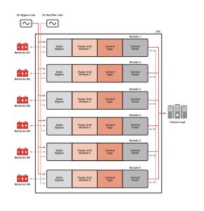
The architectural response is to remove the shared coordination point entirely. Distributed Decision Making, DDM™, requires that each module evaluates its own inputs, makes its own transfer decision, and executes its own isolation without querying a shared controller. Each module runs its own transfer logic against its own sensing inputs, references its own protection thresholds, and executes its own isolation without any handshake to a peer or supervisor.
The specification consequence is direct: you cannot verify per-module independence from a one-line diagram alone. The diagram shows power topology, not control-layer routing. Verification requires the control architecture documentation and FAT test scripts that demonstrate a module executing a transfer with the arbitration bus disconnected. If that test is not in the commissioning script, per-module independence is a specification claim, not a verified property.
Why the electrical layer has to reinforce the control layer
Distributed control is only half the answer. If the modules still share a single bypass electrical path, a local fault that forces one module to bypass forces all of them, because the electrical layer collapses what the control layer worked to keep independent. Per-module bypass paths close that gap: each module’s bypass terminates at its own bypass switch rather than at a shared bus, so the bypass state of one module is not visible as a shared bus condition to neighbouring modules.
That is the structural property that keeps a local fault local. When a module transfers to bypass, the transfer is confined to that module’s own path. Adjacent modules continue in online double-conversion with their own arbitration intact. The electrical topology reinforces what the control topology decided, rather than undoing it at the bus. Maintenance on one module does not require a system-wide bypass event, which is what makes concurrent maintainability a real operational capability rather than a paper claim.
A one-line diagram proves feed separation, not control independence. The convergence-point method in this guide is how design authorities find the shared controller or bypass bus a diagram alone won’t show.
What to trace before you count modules
Evaluating a no-SPOF claim requires locating where decision-making and bypass converge, not counting redundant hardware. An engineer who counts modules and stops there will miss the shared controller and shared bypass bus that make the no-SPOF claim false. Fault-domain separation is validated by tracing control wiring and bypass switching paths in the vendor’s control architecture documentation — not by reading the power one-line diagram.
Most vendor submittals reflect this bias: they include power topology in detail and omit the control architecture. You have to request the control-layer diagram, the bypass switching schematic, and the fault-arbitration description as explicit basis-of-design deliverables. If any of the three cannot be produced, the fault-domain separation claim is unverifiable.
Behaviour-validated commissioning requires FAT, SAT, and IST sequences that test load swings, failover, and abnormal states, synchronised step-load injection representative of a GPU cluster ramp, a simulated single-module fault under dynamic load, and a bypass transfer on one module while the remainder continues in double-conversion. A no-SPOF topology never tested against synchronised load-swing behaviour is a design claim, not a commissioned property.
Where the availability number actually comes from
Once convergence points have been located and fault-domain separation verified, the availability figure is no longer a vendor claim, it is derived from three measurable architectural properties: fault containment scope, control-layer independence, and MTTR. MTTR is determined by fault-domain scope and module replaceability, not by the service-level agreement negotiated after commissioning. A self-isolating fault domain with hot-swap modules produces a structurally lower MTTR than a shared-bus topology requiring full system shutdown for the same repair, because the repair envelope is defined by the hardware.
In DARA that repair envelope resolves to an MTTR of 2 minutes 35 seconds, a module replaced on a live system, no load transfer to bypass, the fault domain already isolated before the technician arrives. That figure is not a service-level target; it is what the hardware permits, which is why it belongs in the design basis rather than the maintenance contract. Feed it back into the availability expression
A = \frac{\text{MTBF}}{\text{MTBF} + \text{MTTR}}and the result is nine nines, 99.9999999%.
The number is worth stating precisely because of where it comes from: it is not a headline, it is the arithmetic consequence of fault containment scope, control-layer independence, per-module bypass, and an MTTR measured in single minutes because no repair requires exposing the critical bus. An engineer can check every term. That is the difference between an availability figure a vendor asserts and one a design authority can derive and defend.
The procurement consequence follows directly: MTTR is a design specification that belongs in the equipment schedule alongside capacity, efficiency, and footprint. Leaving it to the service contract means accepting that the same physical repair will take longer on a topology that exposes the critical load during the work, and that the availability calculation the owner reviews will not survive the first correlated load event.
Tier alignment that survives the audit
An operator who selects a topology for a Tier pathway without verifying control-layer independence will find that the Tier label survives the audit and the operational behaviour does not. Per-module bypass supports the Tier III concurrent-maintainability objective without a system-wide bypass event, but only if the commissioning script demonstrates one module transferred to bypass while the remainder continues in double-conversion against a live load profile. If that scenario is not tested, alignment is asserted from the diagram rather than verified from the installed system.
Supporting Tier IV fault-tolerance objectives requires that any single fault cannot produce a system-wide state change, which excludes topologies with shared controllers or shared bypass buses regardless of module count. The shared coordination point that survives specification will also survive commissioning, and will surface only under the load event no test exercised.
Nine nines only holds if MTTR, fault containment, and control-layer independence are commissioned properties, not assumptions carried from the datasheet. This guide shows the math and the FAT/SAT/IST evidence a design authority can check.

If you’re evaluating a live AI data center project, request an engineering review (ADR). Engineering-led · No sales pitch. Request an engineering review
FAQ
Is adding more UPS modules the same as removing single points of failure?
No. Module count addresses capacity redundancy; it does not address whether control and bypass paths converge at a shared component. A parallel system with many modules can still route every decision through one controller or one bypass, which is the actual failure surface.
Why do AI and HPC workloads change what redundancy has to prove?
GPU clusters produce correlated load transients and harmonic content that steady-state testing does not represent. Redundancy has to hold under those transients, not just under a load-bank ramp, which shifts the burden from nameplate to behaviour.
How do I identify a shared coordination point on a one-line diagram?
Trace the control signalling and the static bypass path across all parallel modules. If either terminates at a single controller, a single bypass switch, or a single arbitration bus, that node is a shared coordination point regardless of how many modules feed it.
The trade-off is now visible: a topology can align with the Tier III/IV pathway on the diagram and still drop the entire critical load the first time a GPU cluster ramps in synchrony, because the shared controller and shared bypass bus were never on the one-line diagram and never tested under behaviour. The question the article cannot answer alone is whether the specific control-layer routing, per-module bypass topology, and abnormal-state test script in front of you actually eliminate the convergence point… or only relabel it.
Download the AI Data Center Power Resilience Guide to evaluate redundancy architecture using convergence-point analysis and fault-domain-separation criteria — including the five questions to put to any UPS vendor before you specify.
References
-
- The Evolving Power Architecture of AI Data Centers — National Academy of Engineering (NAE) (2025-05-08)
- AIOps Architecture in Data Center Site Infrastructure Monitoring — PubMed Central (peer-reviewed) (2022-07-20)
- Roadmap: The AI Data Center Stack — Bessemer Venture Partners (2025-05-19)
- Data Center Power Solutions — Infineon Technologies (2025-07-07)
- Distributed Data Center Architecture: Ensuring Scalability — Gable.ai (2024-03-04)
This article draws on Centiel’s internal engineering documentation and field experience in AI and Colocation Data Center power infrastructures.