Modular UPS For AI Data Centres
Redundancy Architecture

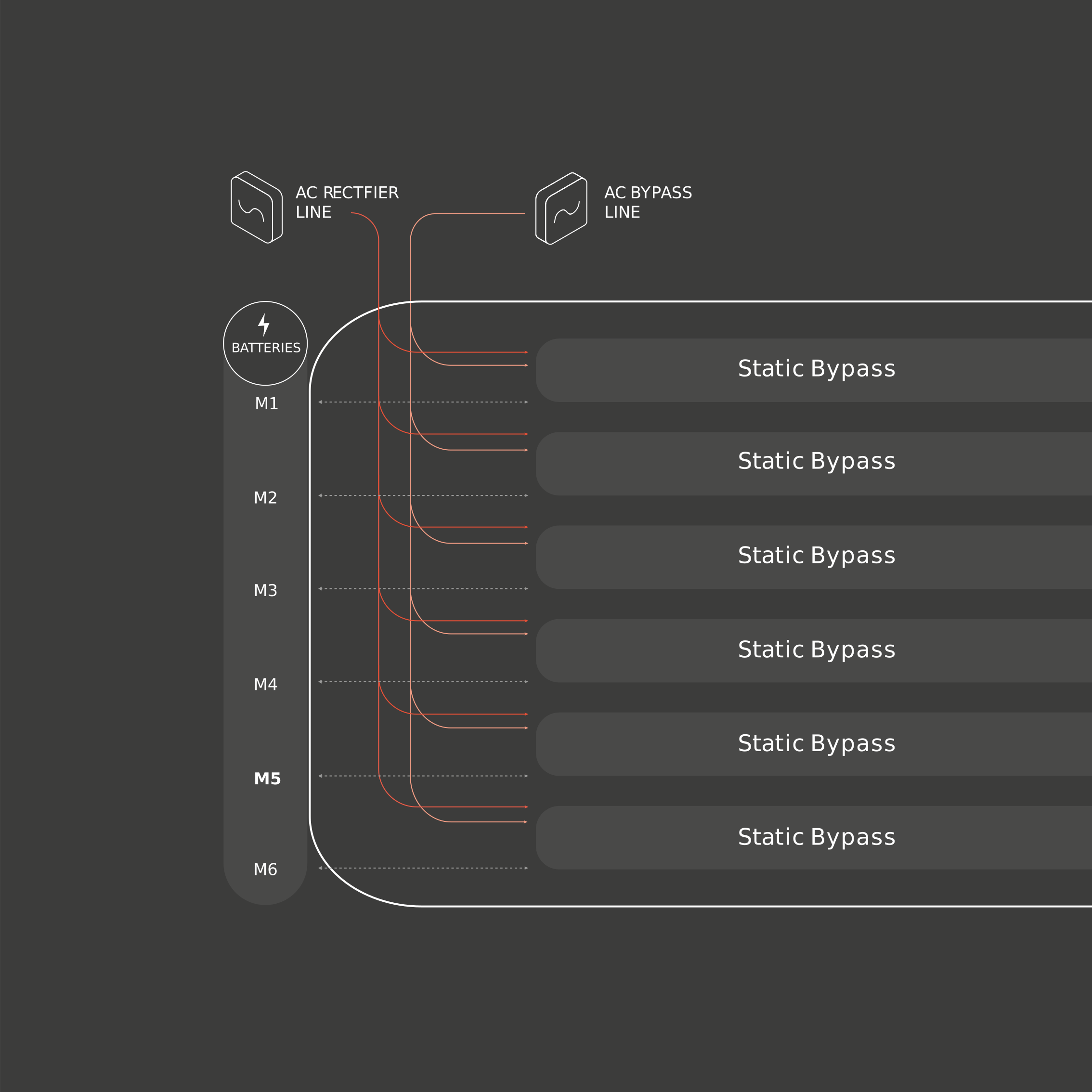
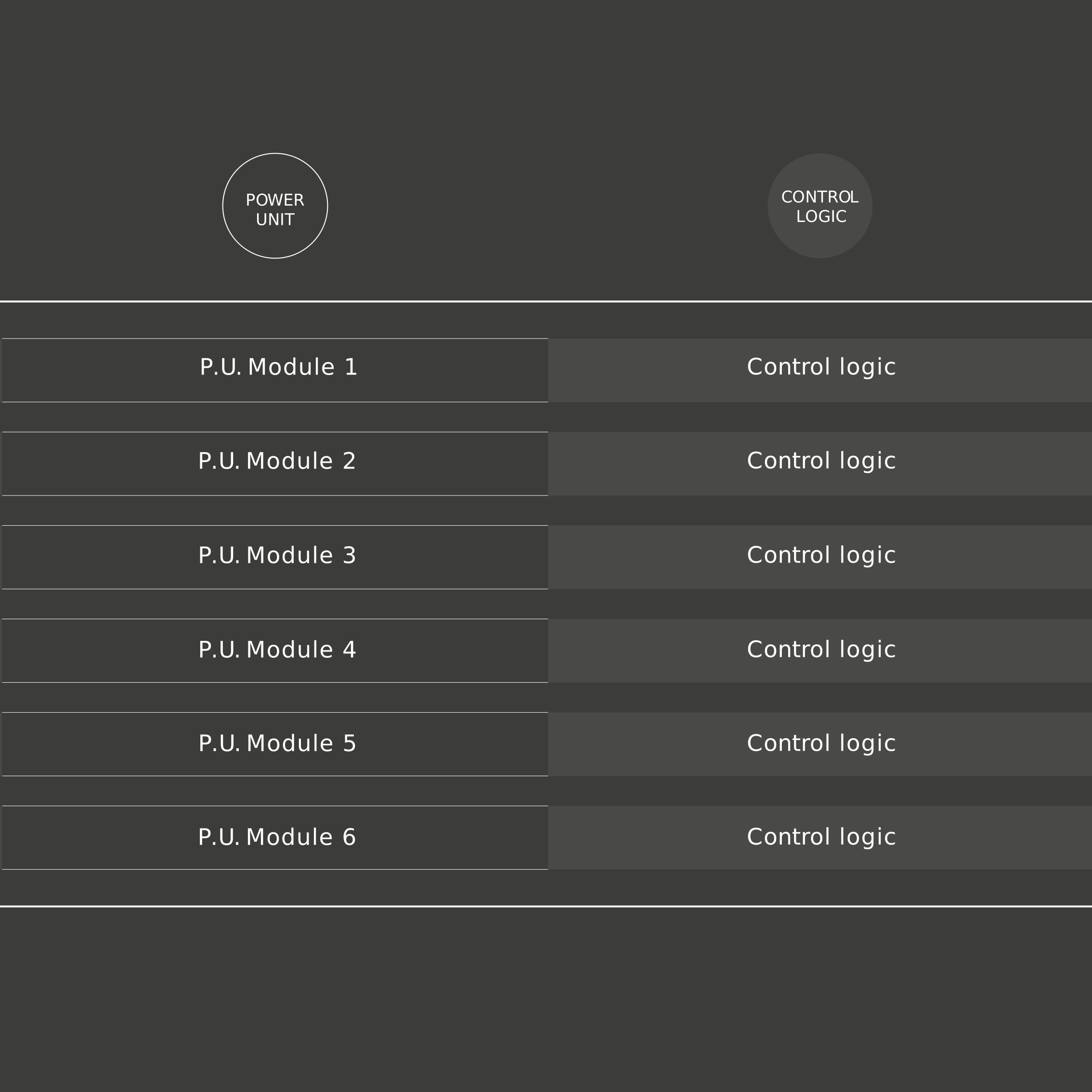
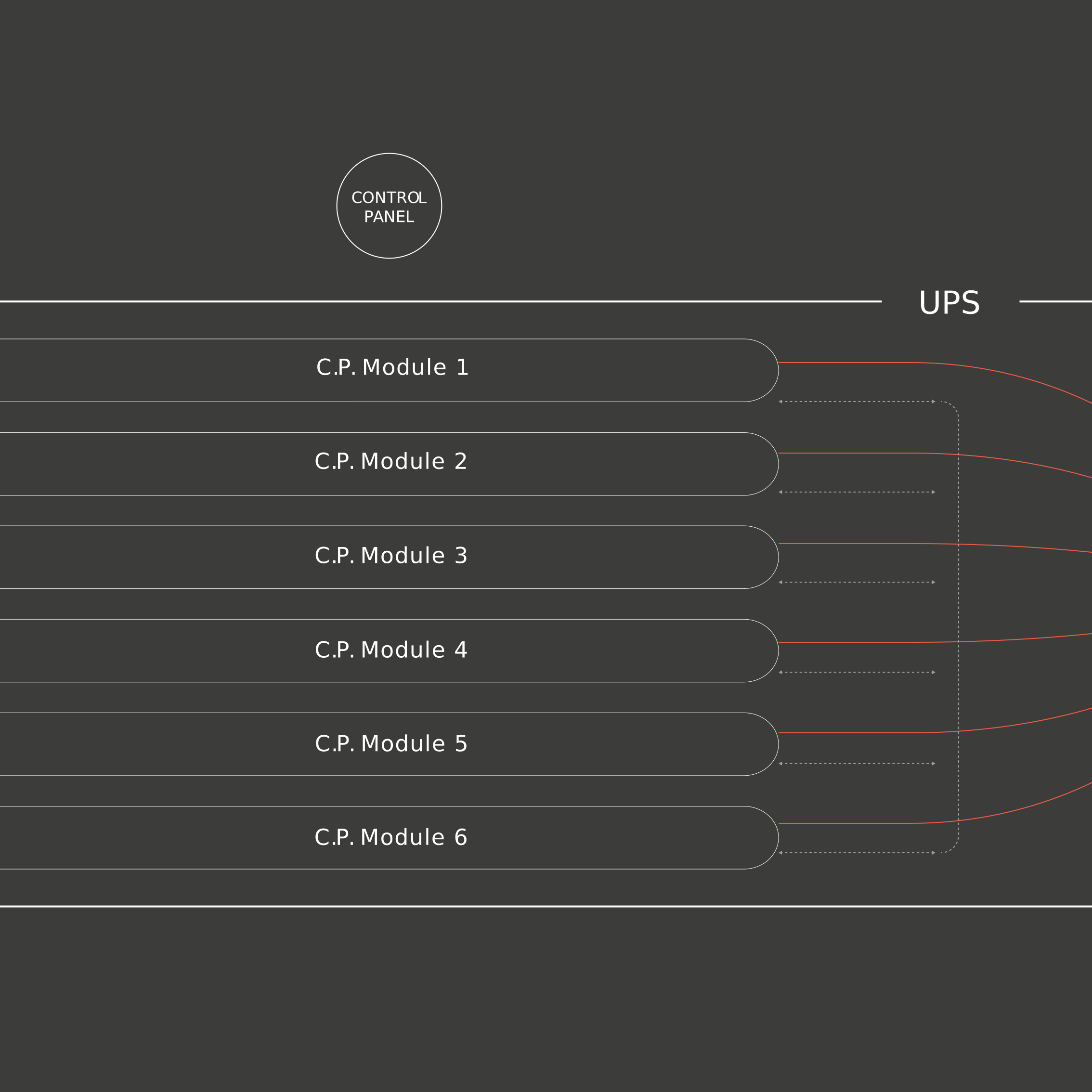
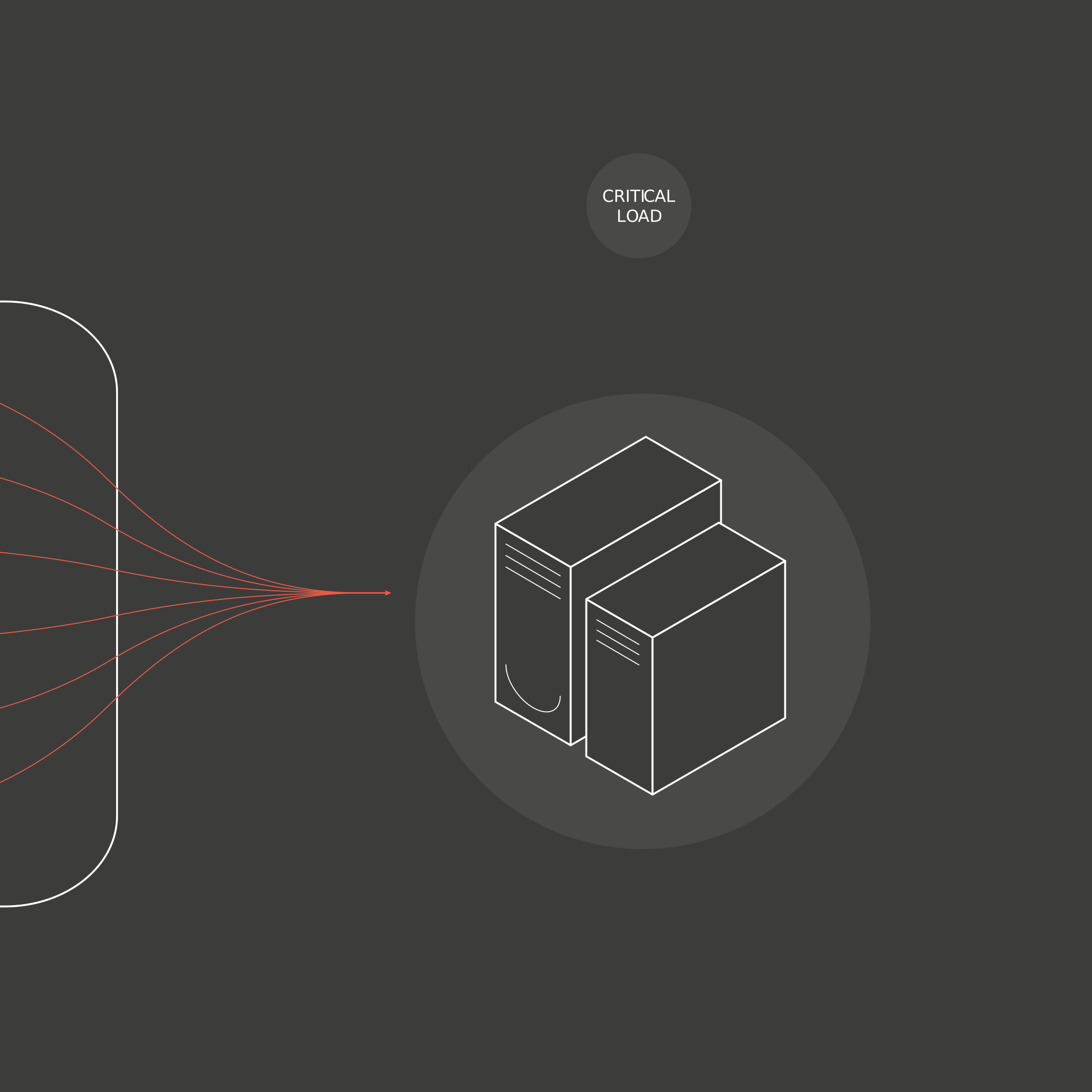
N+1 on a single control board isn’t N+1

A single control board. A single static bypass. A shared parallel bus. Each one a point where everything depends on one component. Module count doesn't change that. Topology does.

Modular UPS For AI Data Centres
Built for AI Load Volatility

The UPS spec passed. The AI load didn't care.

When a training job starts, every GPU ramps simultaneously. The load concentrates, it doesn't diversify. The real test isn't commissioning. It's the first production run.

Up to 9 nines

Designed UPS Availability

97.6%

True online VFI efficiency.

Swiss-made

Designed, built and tested in Switzerland.

In AI infrastructure, a power failure doesn’t pause the workload. It stops it. Every GPU-hour since the last checkpoint is gone.

Downtime is no longer a pause. It is an erasure.

One in five outages now costs more than €1M. That consequence lands before the root cause is identified while the cluster is still down and the GPU capacity it was built to run sits idle.

The person who owns the architecture decision owns the outcome. That is why this decision deserves evidence before the PO: the one-line diagram, the availability model, the field record.

The UPS decision outlasts the GPUs it protects.

A UPS for an AI facility is bought once and runs through several GPU generations. Two things decide whether it was the right call: what it costs over its life, and how much of the building had to change to fit it.

PODS ARE NOW THE AI DEPLOYMENT MODEL

ePOD is not a packaging option. It's how AI power infrastructure is built.

Prefabricated power pods have become the dominant deployment model for high-density GPU infrastructure compressing timelines, enabling repeatable design, and scaling in discrete increments alongside AI compute expansion.

1 MW PER SQUARE METER

In AI data centers, the UPS footprint is a thermal budget decision.

At 40–130+ kW per rack, every square metre carries a thermal consequence. Space consumed by the UPS is space unavailable for CDUs, liquid cooling distribution, and thermal buffer capacity. A direct constraint on how many GPU racks the facility can operate.

AIRFLOW THAT FOLLOWS THE COOLING DESIGN

Airflow configuration is an engineering decision, not a default setting.

GPU clusters run at sustained high load. The UPS thermal profile, how the cabinet dissipates heat and in which direction, must be compatible with the facility’s cooling architecture, not imposed on it.

TOP OR BOTTOM ENTRY, ONE SMOOTH BEND

How the cable enters the cabinet is a thermal and mechanical engineering decision.

Large cross-section cables, 300mm² and above, create mechanical stress and thermal consequences depending on how they enter the cabinet.

A forced double bend in a confined, enclosed space limits heat dissipation and accelerates cable degradation.

BUSBAR OR CABLE: A PROJECT DECISION

The connection method adapts to the facility. The facility does not adapt to the cabinet.

Full flange connection across all busbars, with multiple flange types to match the project’s busbar specification.

Or fully cabled. For POD deployments, AC IN/OUT follows whichever method the POD manufacturer requires.

Eliminate failure paths from the topology

How DARA removes SPOFs at the architecture level. DDM explanation, SPOF analysis, and availability mathematics.

Validate the design against AI load

How the architecture performs against correlated GPU ramp events and sustained high-density load profiles conventional load banks can’t simulate.

Protect the commissioning schedule

How 4–6 week typical lead time works in practice: production slots, delivery window, and what protects your critical path.

Build the lifecycle cost case

30-year economics: acquisition, 97.6% efficiency, one capacitor change, no mid-lifecycle replacement in a format finance accepts.

Why Centiel Exists

Centiel was created to solve a structural problem in mission-critical power: systems that only reveal their weaknesses once they are live. This is the engineering intent behind every architecture decision that follows.

Disclaimer

Performance figures are based on architectural modelling and configuration-specific assumptions. Actual performance depends on system configuration, installation environment, maintenance practices, and operating conditions.

Tier certification is granted by independent third-party assessment bodies and depends on full compliance with facility design.
Typical factory lead time is four to six weeks from confirmed order and final technical release, subject to configuration, production capacity, and prevailing supply conditions.

Download: AI Data Centre Power Resilience Guide